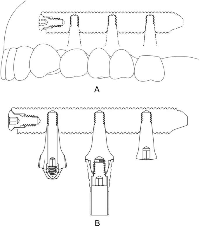
Figure 1. Schematic drawing of the transmaxillary implant. Perforation is made using the 2.0 mm lance implant, for giving guidance and stability to the next drill, using the 3.0 mm implant
Figure 1. Schematic drawing of the transmaxillary implant
author: Gino Kopp,Joo Cezar Zielak,Suyany Gabriely Weiss,Fernanda Kopp,Tatiana Miranda Deliberador | publisher: drg. Andreas Tjandra, Sp. Perio, FISID

Serial posts:
- Long transmaxillary implants
- Background: Long transmaxillary implants (1)
- Materials and methods: Long transmaxillary implants
- Materials and methods: Long transmaxillary implants (2)
- Materials and methods: Long transmaxillary implants (3)
- Results: Long transmaxillary implants
- Discussion: Long transmaxillary implants
- References: Long transmaxillary implants
- Figure 1. Schematic drawing of the transmaxillary implant
- Figure 2. Maxillary computed tomography. a Axial view. b Coronal view
- Figure 3. Surgical guide
- Figure 4. Insertion of the implant
- Figure 5. Mini-pillar guide
- Figure 6. Tomographic scan of the follow-up
- Figure 7. Panoramic radiography of the follow-up
- Figure 8. Final aspect
- Table 1 Comparison of OHIP-14