The results of this study compute part of the expected maximum differences in the final clinical implant position when a CAD/CAM surgical guide is used.
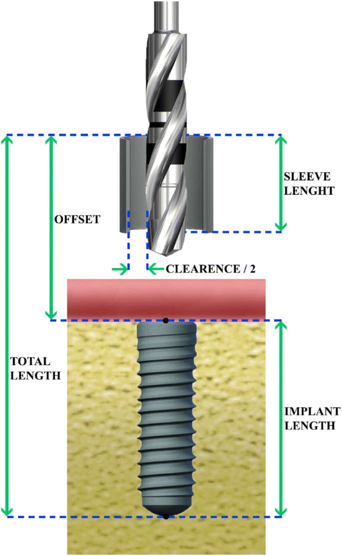
Figure 1. The parameters used for the calculation of the various errors and the deviation of implant axis
author: Dimitrios Apostolakis, Georgios Kourakis | publisher: drg. Andreas Tjandra, Sp. Perio, FISID
Figure 1. The parameters used for the calculation of the various errors and the deviation of implant axis

Serial posts:
- CAD/CAM implant surgical guides: maximum errors in implant positioning
- Background : CAD/CAM implant surgical guides
- Methods & Definition : CAD/CAM implant surgical guides (1)
- Methods & Definition : CAD/CAM implant surgical guides (2)
- Results : CAD/CAM implant surgical guides
- Discussion : CAD/CAM implant surgical guides
- References : CAD/CAM implant surgical guides
- Figure 1. The parameters used for the calculation of the various errors and the deviation of implant axis
- Figure 2. The various errors in implant positioning
- Table 1 Range of various maximum permissible errors as calculated in the present study
- Table 2 Error at the apex (mm) and deviation of implant axis (°) for sleeve lengths 4 and 5 mm
- Table 3 Error at the apex (mm) and deviation of implant axis (degrees) for sleeve lengths 6 and 7 mm
- Table 4 Error at the neck (mm)
- Table 5 Multiple regression coefficients (p < 0.0005)