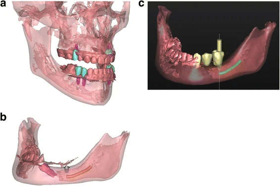
Figure 4. a Patient 1—virtual set-up of the ultimate treatment goal. b Patient 2—virtual set-up of the ultimate implant position. One short dental implant was planned in region 35, based on the location of the mandibular nerve (orange), the impacted 34 (pink) and the bone quality and volume. c Patient 2—virtual set-up of the ultimate prosthetic treatment goal
Figure 4. a Patient 1—virtual set-up of the ultimate treatment goal
author: Marieke A P Filius,Joep Kraeima,Arjan Vissink,Krista I Janssen,Gerry M Raghoebar,Anita Visser | publisher: drg. Andreas Tjandra, Sp. Perio, FISID

Serial posts:
- Three-dimensional computer-guided implant placement in oligodontia
- Introduction : Three-dimensional computer-guided implant placement in oligodontia
- Methods : Three-dimensional computer-guided implant placement in oligodontia
- Results : Three-dimensional computer-guided implant placement in oligodontia
- Figure 1. Patient 1—orthopantomogram (OPT) at age of 13
- Figure 2 a Patient 2—pre-implant orthopantomogram
- Figure 3. a Patient 1—detailed 3D model of the combined data
- Figure 4. a Patient 1—virtual set-up of the ultimate treatment goal
- Figure 5. a Drilling templates of patient 1
- Figure 6. Patient 1—post-operative orthopantomogram (OPT) at age of 18
- Figure 7. Patient 2—post-operative orthopantomogram (OPT) at age of 13. Situation 10 months after implant placement. Three months after starting the orthodontic treatment, the 34 is already erected
- Figure 8. Patient 2—intra-oral situation during orthodontic treatment
- Figure 9. Patient 1—prosthodontic end result 5 months after implant placement
- Figure 10. Patient 1—post-operative evaluation of placement accuracy of the implants